PANELISATION
Overview
Panelisation refers to the process of combining several board artworks onto one panel in order to reduce manufacturing costs. It is common practice to panelise both multiple copies of the same board and several different boards.
You cannot edit Gerber Files when you have a project open. You must close the current project, then open the CADCAM module and load the files.
You can only panelise with boards exported in the Gerber X2 output format. Panelisation with RS274X is deprecated.
You should create your panel in a single Proteus session because some of the placement offset metrics are not stored in the panel file.
Proteus provides facilities to achieve this by using the Gerber module in Editor mode as follows.
- Use the Output Menu > Generate Gerber/Excellon Files command to produce Gerber and Excellon files for each board to be included on the panel.

- Close the current project and then open the Gerber Editor.

- Set the work area in the editor to be the size of the panel via the Technology Menu > Set Board Properties command. This means the automatic placement and offset will correctly start new rows at the right time. It is important to do this before importing the first panel data.

- Go to File Menu > Open CADCAM file... and select the relevant <Project name> - CADCAM READ-ME.TXT file.
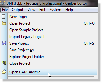
Note that the Open icon will open a project and not a CADCAM file. - Accept the default settings for the layers (these should correspond with the layers you chose to generate at step 1) and check the Panelization mode? checkbox.

- Perimeter spacing is the distance from the edge of the work area, spacing is the gap between incoming boards, and number of copies allows you to autoplace multiple copies of the same PCB.

Click OK. The Gerber Editor will import the CADCAM data for the board and display it as a tagged set of objects. - If the panel is to contain images of additional boards, you can import them into the panel by returning to step 2 above.
- When the panel is complete place a board edge graphic around all the boards. If you followed step 3 above you will simply be tracing over the blue work area.

- When the panel is complete, use the Generate Gerber/Excellon Files command to generate final artwork files for the panel. It is these files that you need to send to your board manufacturer.

- If you want to, you can save the panel project to disk. It will save with a PDSPNL extension to keep it distinct from an actual design project which has a PDSPRJ extension.
The work area for a panelised design is initialised from the Panel template file. If you find that your board manufacturer requires different panel dimensions you can change the work area size on the layout and then use the Technology Menu > Save Panel Template command to override the Panel template with the correct dimensions.
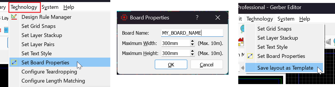
Setting the panel size with the Set Board Properties command and then storing it with Save Panel Template
You cannot panelise a board while a project is open. A Proteus project is the representation of a single board (schematic, layout, 3D Visualisation, BOM, database, etc.) and a panel is clearly a representation of more than one board. Make sure you close the current project before you enter the Gerber Viewer module for panelisation.
How it works
The auto-placement panelisation works very simply by placing the next copy or board at the false origin marker position and then moving the false origin marker by the specified spacing parameter from the edge of the newly placed board. New rows are created automatically when a placed board will overlap the work area, which is why it is a good idea to set your work area to the size of the panel.
What this means is that you can override the automatic placement if you need more control over placement. Simply import boards one at a time, positioning the false origin marker to the desired location.
- Do this by going to the View Menu > Goto Position.
- Set your values and change the Relative to field to be Output Origin.
- Where the mouse is (do not move it), press O on the keyboard to set a false origin. Note that a blue marker will appear.
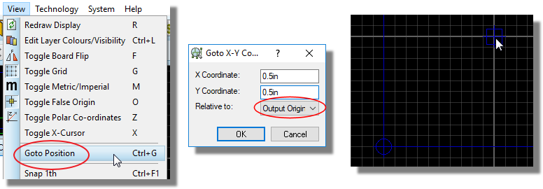
Using Goto Position relative to the Output Origin, then pressing O to drop the blue false origin marker
This will ensure that the next board you bring in will be placed where you want. Note the following points.
- The bottom left corner of the incoming board will always be positioned at the origin marker.
- The rotation of the incoming board will be the same as it was in the 2D Layout. Alternatively, you can specify the rotation while exporting the PCB board. It is better to organise rotation before bringing the board into the panel. You can select and rotate after placement in the panel design but at that stage, of course, you will need to handle the positioning manually.
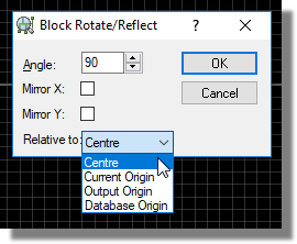
The Block Rotate/Reflect dialogue, setting the angle and the reference point for a placed board
There are a number of points to note about the panelisation process:
- You can add additional text and graphics to the panel as required to designate board IDs and other manufacturing information.
- When importing multiple board images, Proteus will assign new pad and track style codes (D-Codes) for each image. However, when the CADCAM files are re-generated, Proteus will re-combine styles that are actually the same, so that the total usage of aperture and tool codes will not be excessive.
- The resulting set of files may be quite large, especially if the board contains bitmap logos or lots of true-type fonts (these are rasterised). Fortunately, the files are ASCII, and will compress quite well with WINZIP or similar, should you need to transmit them by email.